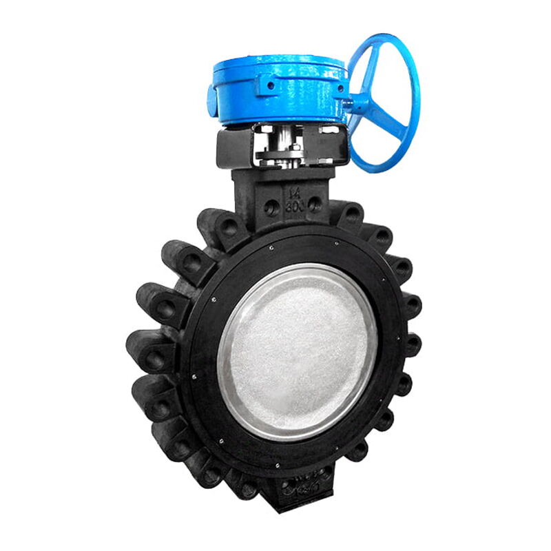
Improving the EMI resistance of electric triple offset butterfly valves is essential for stable operation in complex industrial environments. Variable frequency drives, motors, high-voltage equipment, and switching devices can introduce conducted or radiated interference into power and control circuits. Effective protection combines proper cable routing, physical separation, shielded cables, reliable grounding, power filters, bypass components, isolation transformers, surge protection, and isolated control signals. Stable power supplies, metallic enclosures, and optimized control cabinet layouts can further strengthen actuator immunity. By controlling interference at its source, reducing electromagnetic coupling, and protecting sensitive valve electronics, industrial facilities can improve actuator reliability, minimize control errors, and maintain stable automated valve performance.
Electric triple offset butterfly valves are widely used in industrial automation systems where reliable flow isolation and remote operation are required. They are commonly found in power generation, oil and gas, chemical processing, water treatment, metallurgy, and other process industries.
Unlike manually operated valves, electric triple offset butterfly valves rely on electrical power, actuators, control circuits, position feedback, and sometimes communication networks to perform their functions. This makes their operational reliability closely connected to the quality of the surrounding electrical environment.
Industrial facilities often contain variable frequency drives, motors, transformers, switchgear, high-voltage equipment, contactors, relays, welding machines, and other sources of electromagnetic interference, or EMI. These devices can generate conducted and radiated electromagnetic noise that may couple into power cables and control circuits.
When interference reaches an electric valve actuator, it can cause unstable operation, incorrect feedback, communication errors, unexpected actuator behavior, control signal fluctuations, or even failure to execute an intended command.
For this reason, improving the electromagnetic compatibility of the power supply and control system is an important part of reliable electric valve installation.
Electromagnetic interference occurs when unwanted electromagnetic energy affects the operation of an electrical or electronic device.
In an industrial valve system, interference may be transmitted through power cables, control cables, signal lines, grounding systems, or electromagnetic radiation through the surrounding environment.
The interference may be either conducted or radiated.
Conducted interference travels through electrical conductors. It may originate from switching power supplies, variable frequency drives, motors, contactors, or other equipment connected to the same electrical network.
Radiated interference travels through electromagnetic fields. Strong motors, high-current cables, frequency converters, transformers, and high-voltage equipment can generate electromagnetic fields that couple into nearby wiring.
Understanding these two paths is essential for designing an effective interference-resistant valve installation.
Variable frequency drives are among the most important sources of high-frequency interference in industrial plants.
VFDs rapidly switch electrical power to control motor speed. The resulting voltage and current transitions contain high-frequency components that can propagate through cables and electromagnetic fields.
Motors can also produce electrical noise, particularly during starting, stopping, switching, and variable-speed operation.
Other potential sources include:
An electric triple offset butterfly valve installed close to such equipment may therefore require additional EMC protection.
The electric actuator of a triple offset butterfly valve may contain electronic control boards, position sensors, limit switches, motor drives, communication modules, and power conversion circuits.
These components can be sensitive to transient voltage, high-frequency noise, voltage fluctuations, and electromagnetic fields.
A valve may continue to receive power while its control system becomes unstable due to interference.
Many automated valves use position feedback to communicate whether the valve is open, closed, or at an intermediate position.
If interference affects the feedback circuit, the control system may receive an incorrect signal.
For example, the control system may interpret a partially open valve as fully open or fail to recognize that the valve has reached its commanded position.
Such errors can be particularly serious in automated process systems.
Modern electric actuators may communicate with PLCs, distributed control systems, SCADA systems, or industrial networks.
Electrical interference can introduce communication errors, packet loss, signal instability, or intermittent communication failures.
Therefore, EMI protection should address not only the power supply but also communication and signal wiring.
One of the simplest methods of reducing electromagnetic coupling is physical separation.
Power and control cables for the electric valve should be routed away from strong interference sources such as variable frequency drives, motors, high-current conductors, and high-voltage equipment whenever practical.
The original engineering guidance suggests maintaining approximately 0.5 m or more from strong interference sources where site conditions permit. However, this should be treated as a practical starting point rather than a universal rule.
Actual separation requirements depend on cable construction, current level, frequency spectrum, shielding, grounding, installation method, and applicable EMC requirements.
Long parallel cable runs increase the opportunity for electromagnetic coupling.
When a valve cable runs parallel to a high-current motor cable over a long distance, changing magnetic fields around the power cable can induce unwanted voltages into the neighboring circuit.
Where possible, cables should cross strong interference sources at approximately right angles rather than running alongside them for long distances.
This simple layout principle can significantly reduce inductive coupling.
Longer cables generally provide greater opportunity for capacitive and inductive coupling.
Therefore, wiring should be as short and direct as practical.
This does not mean routing cables in ways that compromise safety, accessibility, maintenance, or equipment spacing. Instead, the objective is to avoid unnecessary loops, excessive cable length, and poorly organized routes.
For electrically noisy environments, shielded cables can provide additional protection.
A double-shielded cable may combine an inner copper braid or aluminum foil shield with an outer metallic layer such as steel armor.
The inner shield can reduce electromagnetic coupling into the conductors, while the outer armor provides additional mechanical protection and can contribute to electromagnetic shielding.
The exact cable structure should be selected according to the application and relevant EMC requirements.
Different shielding materials provide different advantages.
Copper braid provides good mechanical flexibility and effective shielding across a broad range of frequencies.
Aluminum foil can provide excellent coverage, particularly against high-frequency electromagnetic fields, because it can form a nearly continuous conductive barrier around the conductors.
In demanding applications, a combination of foil and braid can provide broader shielding performance than either construction alone.
Steel armor can provide mechanical protection in addition to shielding.
This is particularly useful for cables installed in industrial environments where cables may be exposed to impact, compression, vibration, or other mechanical hazards.
However, cable armor should not automatically be considered a substitute for a properly engineered EMC shield. Its effectiveness depends on continuity, termination, grounding, and installation practices.
A cable shield can only provide effective interference protection when it is properly integrated into the grounding and bonding system.
A poorly terminated shield may become less effective and can potentially introduce new coupling paths.
Shield connections should therefore be designed carefully according to cable type, signal frequency, equipment architecture, and applicable EMC requirements.
The source material recommends single-end grounding to avoid ground loops.
This approach can be appropriate for certain low-frequency analog circuits, where preventing circulating currents is a major concern.
However, grounding strategy is frequency-dependent. At high frequencies, multi-point or 360-degree shield termination at both ends can often provide better EMC performance because it reduces shield impedance and improves high-frequency current paths.
Therefore, it is not appropriate to apply “single-end grounding” as a universal rule to every industrial cable.
Engineers should determine shield termination based on the actual circuit and EMC design requirements.
A grounding resistance target such as 4 ohms or less may appear in some traditional industrial installation practices, but it should not be treated as a universal EMC requirement.
EMC performance depends on bonding impedance, conductor geometry, frequency, shield termination, equipment architecture, and the overall grounding system.
A low DC resistance alone does not guarantee effective high-frequency interference suppression.
For critical installations, grounding and bonding should therefore be designed according to applicable electrical and EMC standards.
A power-line filter can reduce unwanted high-frequency electrical noise entering the electric actuator through its power supply.
Depending on the design, filters can attenuate common-mode and differential-mode interference.
They typically use combinations of inductors, capacitors, and other components to present high impedance to unwanted frequencies while allowing the required power frequency to pass.
Filter selection should consider both the normal operating frequency and the interference spectrum.
The source material suggests selecting a cutoff frequency below the interference frequency but above the equipment operating frequency.
The actual design is more complex because practical filters have attenuation curves rather than a single ideal cutoff frequency.
Engineers should examine the filter's insertion-loss characteristics and verify that it is appropriate for the actual power system and actuator.
Where practical, the filter should be installed near the equipment being protected.
Long cable sections between the filter and actuator can provide opportunities for noise to couple back into the protected circuit.
Good physical separation between the “dirty” input side and “clean” output side of the filter is also important.
If the two sides are routed closely together, electromagnetic coupling can bypass some of the filter's benefits.
High-frequency bypass capacitors can provide low-impedance paths for certain unwanted high-frequency components.
A capacitor installed appropriately across a power supply can help divert high-frequency noise away from sensitive electronics.
Ceramic capacitors are commonly used because they can provide low impedance at high frequencies.
The source material suggests values such as 0.1 μF to 1 μF for high-frequency bypass applications.
However, capacitance should never be selected solely from a generic numerical range.
The correct value depends on the power supply architecture, voltage rating, capacitor technology, transient environment, safety requirements, and equipment manufacturer's design.
In AC mains applications, safety-rated capacitors such as X or Y capacitors may be required depending on where the capacitor is installed.
A bypass capacitor can create safety hazards if it is incorrectly selected or connected.
The component must have an appropriate voltage rating, temperature rating, safety classification, and dielectric system.
Maintenance personnel should not add capacitors to industrial power circuits without understanding the electrical design.
An isolation transformer can separate the downstream electrical circuit from the upstream power source.
A 1:1 isolation transformer can maintain approximately the same nominal voltage while providing galvanic isolation between primary and secondary circuits.
This can help reduce certain forms of conducted common-mode interference and provide additional protection against some transient disturbances.
However, an isolation transformer is not a universal solution to EMI.
Its effectiveness depends on transformer construction, grounding arrangement, frequency characteristics, common-mode capacitance, and the nature of the interference.
Isolation and filtering can sometimes be combined.
The transformer provides galvanic separation, while a properly selected filter attenuates unwanted frequency components.
In a demanding industrial environment, a coordinated combination of isolation, filtering, shielding, grounding, and cable separation can provide significantly better protection than any single measure.
Control signal isolation can be achieved using optocouplers or other galvanically isolated interfaces.
An optocoupler transfers information through an optical path rather than a direct electrical connection.
This can prevent certain unwanted electrical disturbances from traveling directly from one circuit to another.
Modern industrial equipment may also use digital isolators or isolated transceivers, depending on the signal type and communication protocol.
Power cables and low-level signal cables should be routed separately.
The source material recommends keeping strong-current and weak-signal wiring at least approximately 30 cm apart where practical.
Again, this should be considered a practical guideline rather than a universal standard requirement.
The necessary distance depends on voltage, current, cable construction, shielding, frequency, installation method, and the specific EMC environment.
Where possible, power and signal cables should use separate trays, conduits, or routing systems.
For example, a motor power cable from a VFD should not share the same cable tray with a sensitive valve position feedback cable unless the installation has been specifically designed to control electromagnetic coupling.
Physical separation is one of the most cost-effective forms of EMC protection because it reduces coupling at the source.
If power and signal cables must cross, crossing them at approximately 90 degrees can reduce the length over which electromagnetic fields can couple between them.
This is generally preferable to long parallel runs.
The layout inside an electrical cabinet can affect EMI performance.
High-noise components such as VFDs, contactors, switching power supplies, and high-current devices should be separated from sensitive PLC modules, communication interfaces, analog inputs, and low-level signal circuits where practical.
This reduces the chance of radiated and conducted interference coupling into sensitive electronics.
High-current conductors should be routed in a way that minimizes unnecessary loops.
Large conductor loops can increase magnetic coupling.
Where appropriate, supply and return conductors should be routed close together to reduce the effective loop area.
Metal control cabinets can provide electromagnetic shielding when properly bonded.
Paint, corrosion, loose fasteners, or poorly connected doors can increase impedance between metal sections and reduce shielding effectiveness.
EMC bonding should therefore consider the actual high-frequency current path rather than relying only on low-frequency protective earth connections.
A stable power supply can reduce the effects of voltage fluctuations and electrical disturbances on the actuator.
Power supplies should be properly sized and selected for the actuator's starting current, continuous load, transient conditions, and environmental requirements.
Where necessary, surge protection, voltage regulation, UPS systems, or other power-quality measures may be considered.
A metallic enclosure can provide electromagnetic shielding around sensitive electrical components.
The enclosure must be properly bonded and grounded to be effective.
Openings, cable entries, doors, and removable panels should also be considered because electromagnetic energy can enter through poorly designed openings.
Cable glands and entry points are often overlooked in EMC design.
A shielded cable entering a metal enclosure should maintain appropriate shield continuity at the entry point.
For demanding EMC environments, 360-degree shield termination through suitable EMC cable glands can provide better high-frequency performance than long pigtail connections.
EMI and surge are related but not identical problems.
EMI generally refers to unwanted electromagnetic energy that interferes with equipment operation.
A surge is a transient overvoltage or overcurrent event that can cause direct electrical stress or damage.
An electric valve actuator may be exposed to both.
Surge protective devices can help limit transient overvoltage caused by lightning, switching operations, or other electrical events.
Protection should be selected based on the electrical system voltage, grounding arrangement, expected surge environment, and equipment sensitivity.
For critical installations, surge protection may be used at multiple levels, such as the facility distribution panel and the equipment level.
Power protection alone may not be sufficient.
Long signal and communication cables can also act as pathways for transient disturbances.
Where appropriate, signal surge protectors, isolated interfaces, shielded cables, and proper grounding can help reduce the risk of transient damage.
Before commissioning an electric triple offset butterfly valve, technicians should verify cable routing, shield continuity, grounding, terminal connections, power polarity, and separation between power and signal wiring.
This inspection can identify installation errors before the equipment is exposed to operating conditions.
The valve should be operated through its full intended range.
Technicians should verify opening, closing, stopping, position feedback, local control, remote control, and communication functions where applicable.
If practical, the valve should also be monitored while nearby high-power equipment is operating.
For example, technicians can observe valve behavior while VFD-driven motors start, stop, or change speed.
If actuator errors occur only when nearby equipment is operating, electromagnetic coupling should be considered as a possible cause.
Intermittent problems are often difficult to diagnose.
Maintenance teams should record the timing, operating condition, equipment status, and symptoms associated with interference events.
A pattern may eventually reveal that failures occur when a specific motor starts or when a particular VFD changes frequency.
The most effective EMI solution often begins at the source.
If a VFD generates excessive electrical noise, addressing the VFD installation, output cable shielding, grounding, filtering, and switching configuration may reduce interference before it reaches the valve.
This is generally more effective than attempting to protect the valve after interference has already propagated through the system.
The second step is to reduce the coupling path.
Cable separation, shielding, proper routing, enclosure design, and physical layout can reduce radiated and conducted coupling.
The final layer is the equipment itself.
Filters, isolation, surge protection, regulated power supplies, shielded enclosures, and robust control electronics can improve the actuator's resistance to interference.
The strongest EMC design typically combines all three approaches: source control, coupling-path reduction, and receiver protection.
A shielded cable cannot compensate for poor routing and grounding.
If the shield is incorrectly terminated or the cable runs directly beside a high-power VFD cable for a long distance, interference may still occur.
Poor bonding can reduce the effectiveness of shielding and filtering.
Grounding should therefore be treated as an integral part of EMC design.
Placing power, control, and low-level signal cables together can create unnecessary coupling.
Separate routing is generally preferable.
A filter can become less effective if its input and output wiring are routed too close together.
The noisy side and clean side should be physically separated to prevent interference from bypassing the filter.
There is no single grounding strategy that is optimal for every frequency and circuit.
Low-frequency analog signals, high-frequency communication cables, shielded power cables, and safety grounding may require different approaches.
The grounding and bonding system should therefore be designed according to the equipment architecture and applicable EMC standards.
Improving the interference resistance of an electric triple offset butterfly valve is not achieved through one component or one wiring technique. Reliable performance requires a coordinated EMC strategy covering power supply quality, cable routing, shielding, grounding, filtering, electrical isolation, surge protection, control cabinet layout, and actuator design.
Power and signal cables should be separated from high-noise equipment such as variable frequency drives and motors. Long parallel runs should be minimized, while appropriate shielded or armored cables can reduce electromagnetic coupling. Filters, bypass components, isolation transformers, and isolated signal interfaces can further reduce conducted interference when properly designed.
At the equipment level, stable power supplies, metallic enclosures, appropriate cable glands, reliable bonding, and surge protection can improve actuator immunity.
Most importantly, EMC design should not rely on generic rules alone. Cable spacing, shield termination, grounding configuration, filter parameters, capacitor selection, and isolation methods must be verified against the actual electrical system, valve actuator specifications, environmental conditions, and applicable standards.
A well-designed interference-resistant system uses multiple layers of protection. By controlling interference at its source, reducing coupling along the transmission path, and strengthening the immunity of the electric triple offset butterfly valve itself, industrial facilities can significantly improve control stability, reduce unexpected actuator faults, and maintain reliable automated valve operation over the long term.