Modern power plants operate as highly integrated systems in which steam, water, fuel, cooling media, flue gas, and auxiliary fluids must be controlled continuously and safely. Within these systems, valves are no longer viewed simply as mechanical devices for starting or stopping flow. Their ability to respond to control commands, provide reliable isolation, withstand demanding environments, and communicate operating data has become increasingly important.
Electric valves, more precisely valves equipped with electric actuators, have therefore become an important choice for many power-generation applications. Their value comes from the combination of precise actuation, digital communication, local and remote operation, diagnostic capabilities, and relatively straightforward integration with plant automation systems. In power applications, electric actuators are used across water and steam circuits, boiler systems, turbine-related systems, cooling systems, and flue-gas treatment equipment.
However, the selection of an electric actuator should not be based simply on the assumption that electric operation is always superior to pneumatic or hydraulic actuation. Valve size, torque or thrust requirements, operating frequency, fail-safe philosophy, hazardous-area classification, ambient temperature, power availability, and safety integrity requirements all influence the appropriate solution. The real advantage of electric valve actuation is its ability to become a reliable automation node within the wider power-plant control architecture.
Traditional manual valves primarily require operators to travel to the installation location and physically turn a handwheel or operate a lever. This approach may be acceptable for infrequently operated isolation points, but it becomes inefficient when valves must respond to changing operating conditions or participate in automatic sequences.
An electrically actuated valve changes this operating model. The valve becomes an endpoint of the plant's instrumentation and control architecture. Commands can originate from a distributed control system (DCS), programmable logic controller (PLC), safety system, or local control station. Feedback can simultaneously return information such as valve position, end-of-travel status, torque, faults, motor temperature, and other diagnostic parameters.
Modern actuator controls can exchange commands and feedback with a DCS while handling motor switching locally. Advanced actuator systems can also provide event records, torque characteristics, temperature and vibration information, and operating-cycle statistics, creating a substantially richer information interface than a conventional motor-operated valve with basic limit switches.
One of the strongest reasons for using electric actuators in modern plants is their compatibility with industrial automation architectures. Depending on the actuator and control-system design, communication may use conventional discrete signals, analog signals, fieldbus networks, Industrial Ethernet, HART, or other industrial communication technologies.
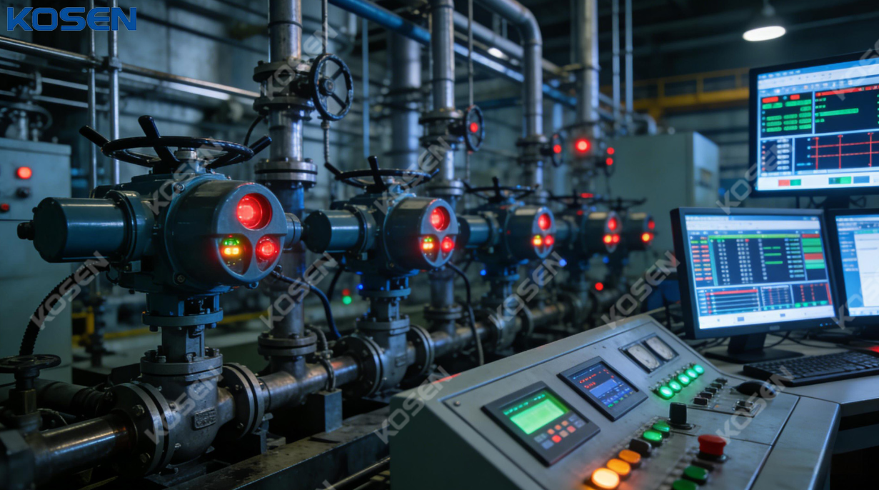
A typical control arrangement may include:
| Plant level | Typical function |
|---|---|
| DCS/PLC | Supervisory control and process logic |
| Communication network | Command and data transmission |
| Actuator controller | Signal processing and motor control |
| Electric actuator | Converts electrical energy into mechanical movement |
| Valve | Regulates or isolates process flow |
| Feedback devices | Position, torque, limit and fault feedback |
This architecture makes it possible to coordinate multiple valves within an operating sequence. For example, a boiler startup sequence may require several valves to open or close according to defined process conditions rather than simply according to manual operator commands.
Modern electric actuator platforms can provide parallel interfaces as well as fieldbus and other process-automation interfaces, allowing them to be adapted to different plant control architectures.
Not every power-plant valve needs continuous positioning. Many large isolation valves operate primarily in open-close service. However, numerous process applications require the valve to assume intermediate positions and continuously adjust flow.
Examples include:
In these applications, the actuator must do more than simply move the valve from one end position to another. It must provide controlled movement and repeatable positioning.
Electric actuators can be configured for different duty types, including open-close, positioning, and modulating service. Manufacturers also provide different actuator configurations for multi-turn, part-turn, and linear movement, depending on the valve's mechanical requirements.
The practical value of positioning accuracy is particularly apparent in processes where a small change in valve opening produces a meaningful change in flow. An actuator that repeatedly reaches the commanded position can help maintain more stable process conditions.
For example, in a steam temperature-control system, the control system may adjust a spray-water valve in response to measured steam temperature. If the actuator responds consistently to small changes in the command signal, the control loop can maintain the desired operating point without excessive oscillation.
This does not mean that every electric actuator automatically provides superior control performance. The overall result depends on actuator resolution, gearbox characteristics, valve sizing, deadband, control-loop tuning, process dynamics, and valve flow characteristics. Electric actuation is one component of the control loop rather than a substitute for proper system engineering.
Power plants contain numerous locations with elevated temperatures, mechanical vibration, steam exposure, moisture, dust, and potentially corrosive atmospheres. An actuator installed in such an environment must be selected according to the actual ambient conditions rather than simply the temperature of the process fluid.
The actuator itself may be separated from the hottest portion of the process by the valve stem, bonnet, extension, insulation arrangement, or mechanical design. Nevertheless, radiant heat and surrounding ambient temperature can significantly affect motor insulation, electronics, lubricants, seals, and enclosure performance.
Power-industry actuator products are specifically developed with considerations such as voltage variation, vibration, temperature, and installation orientation in mind.
Moisture and dust ingress can damage electrical components, particularly in outdoor installations, cooling-water areas, wastewater systems, and locations subject to washing or condensation.
The IP rating defined under IEC 60529 provides a standardized method of classifying protection provided by electrical enclosures against ingress.
For power-plant applications, engineers therefore need to consider:
A high IP rating by itself does not guarantee suitability for every environment. The complete actuator, cable glands, electrical connections, coatings, and installation arrangement must be considered.
One of the most important engineering principles in electric valve automation is that actuator selection must begin with the valve's mechanical requirements.
Different valves require different types of movement:
| Valve type | Typical actuator movement |
|---|---|
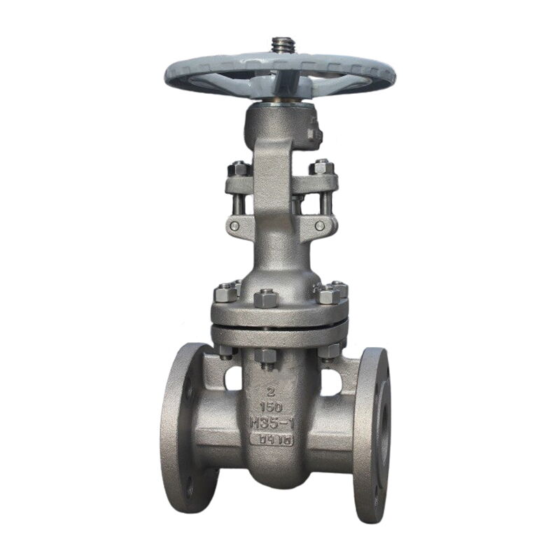
| Gate valve | Multi-turn or linear through suitable transmission |
| Globe valve | Linear or multi-turn through stem movement |
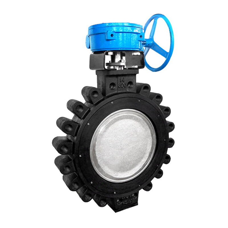
| Butterfly valve | Part-turn |
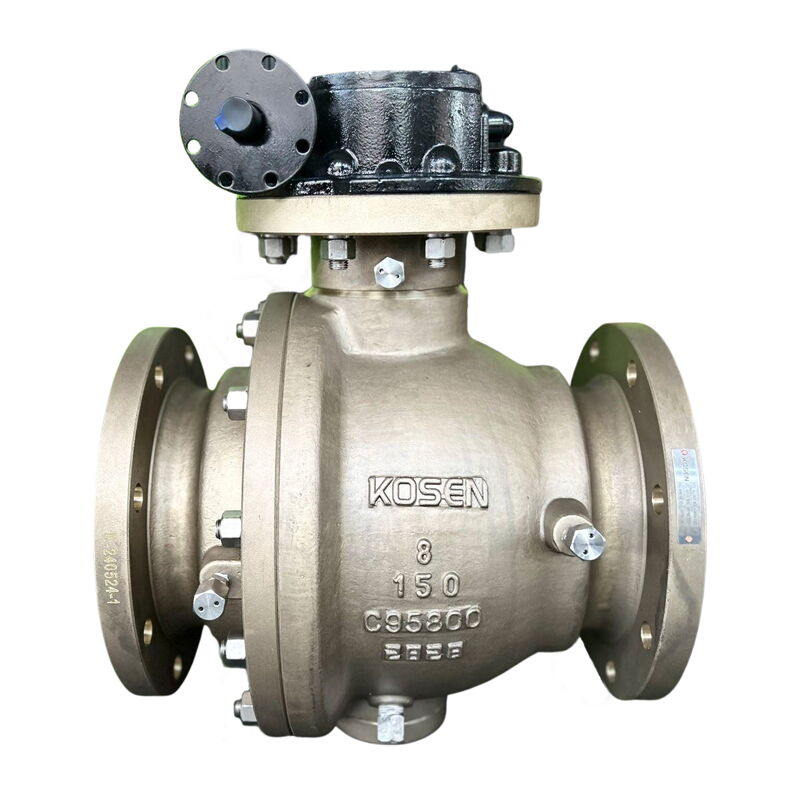
| Ball valve | Part-turn |
| Plug valve | Part-turn or multi-turn depending on design |
| Linear control valve | Linear thrust |
For rotary valves, torque is normally the primary sizing parameter. For linear valves, thrust becomes particularly important. Engineers must consider not only the nominal operating torque or thrust but also seating requirements, breakaway forces, differential pressure, friction, temperature effects, and potential valve degradation.
An undersized actuator may fail to move the valve under actual process conditions. An excessively oversized actuator can introduce unnecessary cost and may create excessive mechanical loading if the torque protection and valve interface are not properly coordinated.
Valve seating conditions can change over the operating life of a power plant. Deposits, corrosion, thermal expansion, packing friction, or changes in differential pressure can increase the force required to move the valve.
Modern actuator controls can monitor torque and use torque-based shutdown or protection functions. Some systems can also record torque characteristics, providing useful information for maintenance and troubleshooting.
This capability is particularly valuable because abnormal torque can indicate a developing mechanical problem before complete valve failure occurs.
Power interruption is one of the most important issues when evaluating electric valve actuation in a power plant. A common advantage of electric actuators is their ability to retain a defined valve position when electrical power is removed, depending on actuator design and process requirements.
However, an important engineering distinction must be made: power-loss position retention is not automatically equivalent to a fail-safe function.
A conventional electric actuator may simply stop when power disappears, leaving the valve approximately where it was. This can be desirable for some process applications. In other applications, the valve must move to a predefined safe position after a power failure.
A genuine fail-safe function may require:
Some electric actuation solutions use stored mechanical energy or other backup arrangements to achieve defined emergency movement without normal power supply.
Therefore, the correct question is not simply whether an electric valve can operate without power, but what the valve is required to do when normal power is unavailable.
For safety-critical applications, the actuator and valve must be considered as part of the complete safety function. The required safety integrity level, response time, diagnostic coverage, redundancy, and proof-test strategy can all influence equipment selection.
Some intelligent electric actuator systems are available with safety-related configurations capable of implementing defined emergency opening or closing functions and achieving specified SIL levels under applicable certification conditions.
The specific safety capability, however, must always be verified against the certified product configuration and the plant's safety requirements rather than assumed from the presence of an electric motor.
Pneumatic actuators are widely used in industrial plants and remain highly valuable where fast response, inherent fail-safe action, or hazardous-area considerations make compressed air particularly suitable. Nevertheless, pneumatic valve automation requires an instrument-air infrastructure.
That infrastructure can include:
Electric actuators eliminate the need for instrument air at the actuator itself. This can simplify the infrastructure for applications where electrical power is already readily available.
The economic advantage therefore depends on the complete plant design. An electric actuator should not be described as automatically cheaper than a pneumatic actuator. Instead, engineers should compare the total system cost, including actuator, power supply, control infrastructure, compressed-air generation, maintenance, energy consumption, and required redundancy.
An electric actuator generally consumes significant power while its motor is operating, but the motor is not necessarily running continuously when the valve is stationary. Intelligent actuator electronics may still have standby consumption, so the actual energy profile depends on the product and application.
For valves that move only occasionally, this operating pattern can make electric actuation attractive from an energy perspective. For frequently modulating valves, however, motor duty cycle and actuator efficiency must be evaluated carefully.
The correct lifecycle calculation should therefore consider:
Total energy cost = operating energy + standby/control energy + auxiliary-system energy + maintenance-related energy
This approach provides a more meaningful comparison than simply comparing the rated motor power of an electric actuator with the compressor capacity of a pneumatic system.
The development of intelligent electric actuators is changing their role from simple motion devices into sources of equipment information.
A modern actuator can potentially record:
Advanced actuator controls can record time-stamped events, torque characteristics, temperature, vibration, starts, and motor running time.
This information can be integrated into plant asset-management strategies. Instead of waiting for a valve to fail, maintenance teams can analyze changes in operating behavior and investigate abnormal trends.
Consider a valve that normally requires a relatively stable torque profile. If the measured torque gradually increases over several operating cycles, possible causes may include packing friction, stem problems, deposits, corrosion, bearing degradation, or process-related changes.
The actuator does not necessarily identify the exact root cause by itself, but it can provide evidence that justifies inspection.
This creates a maintenance chain:
Data collection → Trend analysis → Abnormality detection → Inspection → Corrective action
Such an approach can reduce unexpected downtime and improve maintenance planning, particularly in plants where access to valves is difficult or where an unexpected valve failure could interrupt production.
Boiler systems contain numerous valves responsible for controlling water, steam, blowdown, drains, vents, and auxiliary flows. Electrically actuated valves can be used for both isolation and controlled positioning, depending on the process requirement.
Feedwater-related applications can demand accurate positioning because changes in feedwater flow directly influence boiler operating conditions. The actuator therefore needs suitable thrust or torque capacity, adequate positioning resolution, appropriate duty classification, and reliable feedback.
Steam systems impose demanding requirements because of high temperature, pressure, thermal cycling, and the consequences of incorrect valve operation.
Electric actuators can be used on auxiliary steam valves, bypass systems, isolation valves, and other applications where electrically controlled movement is appropriate. In turbine-related applications, response speed and fail-safe behavior become especially important because the acceptable response time may be determined by the turbine protection and process-control philosophy.
Electric actuator manufacturers identify turbine control and bypass applications as areas requiring precise and reliable actuation.
Cooling systems frequently contain large butterfly, gate, or other rotary and linear valves. These valves may be installed outdoors and can therefore face moisture, temperature variation, corrosion, and long periods of intermittent operation.
Electric actuators can provide remote operation while eliminating the need to manually access large valves. Intelligent position feedback can also allow operators to verify whether a valve has reached its commanded position.
Electric actuation is also relevant to hydropower facilities. Applications include inlet and outlet shut-off valves, bypass valves, water-level control, turbine control, sluice gates, and other hydraulic structures.
Modern actuator systems can support DCS integration through parallel signals, fieldbus, Industrial Ethernet, and HART technologies, while specialized fail-safe arrangements can provide defined emergency movement when required.
The presence of an electric motor naturally introduces electrical considerations. If an actuator is installed in an area where flammable gas, vapor, or combustible dust may create a hazardous atmosphere, the actuator's certification and construction must match the applicable area classification.
This means engineers should examine:
IEC 61010-2-202 specifically addresses safety requirements for electrically operated valve actuators and solenoids used in industrial process or discrete control environments, although functional-safety requirements are outside its scope.
For hazardous locations, additional standards and certification requirements may apply depending on the jurisdiction and protection concept.
A valve used for an emergency shutdown function should not be treated as a conventional process-control valve simply because it has an electric actuator.
Functional safety requires consideration of the entire safety loop, including sensors, logic solvers, output circuits, actuator, valve, feedback, diagnostics, testing, and maintenance procedures.
Consequently, specifying an actuator as "SIL capable" is not sufficient by itself. Engineers must verify whether the complete safety function achieves the required performance under the actual architecture and operating conditions.
Even a high-quality electric actuator can experience premature failure if it is poorly installed. The valve and actuator should be correctly aligned, and the mechanical interface must be suitable for the specified torque or thrust.
Important installation considerations include:
Incorrect limit-switch settings are particularly important because they can prevent the valve from reaching its intended position or cause unnecessary mechanical loading.
Maintenance programs should consider both the mechanical valve and the actuator. A practical inspection regime may include checking enclosure condition, cable glands, electrical connections, handwheel operation, valve travel, abnormal noise, torque trends, and fault records.
For intelligent actuators, historical operating data should be incorporated into maintenance decisions rather than ignored. Diagnostic information can provide useful early indicators of developing mechanical or electrical problems.
A technically sound selection process should begin with the process requirements rather than the actuator brand or nominal motor size.
Determine whether the valve is intended for:
The function determines the required actuator duty and control philosophy.
Calculate the actual valve operating requirement, including breakaway, running, seating, unseating, differential-pressure, and temperature effects. Apply an appropriate engineering margin without excessively oversizing the actuator.
A valve that moves twice per week has very different actuator requirements from a valve that continuously modulates during normal operation.
Duty classification should therefore be considered carefully. Some electric actuator families distinguish between open-close and modulating service, with different permissible operating cycles and thermal requirements.
The plant engineer should define whether the actuator will communicate using:
The interface should be compatible with the DCS, PLC, safety system, or asset-management platform.
Specify whether the valve should:
This requirement can fundamentally change the actuator design.
Electric and pneumatic actuators should be compared according to application requirements rather than general assumptions.
| Factor | Electric actuation | Pneumatic actuation |
|---|---|---|
| Power source | Electrical power | Compressed air |
| DCS integration | Strong digital integration capability | Strong integration capability |
| Position control | Well suited to precise positioning | Also highly capable |
| Instrument-air infrastructure | Not required | Required |
| Power-loss behavior | Depends on actuator design | Depends on pneumatic fail-action design |
| Diagnostics | Advanced options available | Available with suitable smart positioners |
| Hazardous areas | Requires appropriate electrical certification | Often attractive for hazardous environments |
| Large valve applications | Widely used | Widely used |
| Modulating service | Available | Widely used |
| Fail-safe options | Requires appropriate design | Often straightforward with spring-return systems |
This comparison demonstrates why the question "Are electric valves better?" is technically incomplete. The appropriate choice depends on the process, safety requirements, infrastructure, and operating philosophy.
Power-plant valve automation projects normally involve multiple standards rather than one universal “electric valve standard.” The applicable requirements depend on the valve, actuator, electrical system, hazardous area, control architecture, and safety function.
IEC 61010-2-202 provides safety requirements specifically addressing electrically operated valve actuators and solenoids in industrial process and discrete-control environments. IEC 60529 provides the IP-code framework for enclosure protection against ingress. Other valve, actuator, electrical, EMC, hazardous-area, and functional-safety standards may apply depending on project requirements.
For procurement, technical documentation should normally include:
Good documentation is particularly important in power plants because equipment may remain in service for decades, often with multiple generations of maintenance personnel and control-system upgrades.
The development of digital power plants is gradually changing what operators expect from field equipment. A valve is increasingly expected not only to execute commands but also to communicate its operating status and provide useful diagnostic information.
An intelligent actuator can therefore become part of the plant's digital infrastructure. Instead of a simple signal such as "open" or "closed", the control system can potentially receive richer information about position, torque, operating history, alarms, and equipment condition.
This supports the broader development of condition-based maintenance and plant asset management. Digital communication technologies can also reduce wiring requirements and provide standardized interfaces between field equipment and higher-level automation systems.
In this context, the electric valve is not simply replacing a manual valve. It is becoming an intelligent field device within the power plant's automation architecture.
The growing use of electric valve actuation can ultimately be explained through several interconnected advantages:
1. Automation: Electric actuators can receive commands from DCS and PLC systems and return operational feedback.
2. Precise positioning: Suitable electric actuators can provide controlled and repeatable valve movement for positioning and modulating applications.
3. Digital connectivity: Modern actuator controls can support conventional signals as well as fieldbus, Industrial Ethernet, HART, and other communication technologies.
4. Diagnostic capability: Advanced systems can record torque, temperature, vibration, operating time, starts, and events, supporting condition monitoring.
5. Flexible installation: Electric actuators do not require an instrument-air network at every valve.
6. Adaptability: Different configurations are available for multi-turn, part-turn, and linear valve movements.
7. Safety integration: Specialized actuator configurations can support defined safety functions when properly engineered and certified.
These advantages explain why electric actuation has become an important technology in modern power-generation facilities.
Electric valves have become an important part of modern power-plant automation because they combine mechanical valve operation with electrical control, digital communication, feedback, and increasingly sophisticated diagnostics. Their ability to integrate with DCS and PLC architectures makes them suitable for applications ranging from routine isolation to precision flow regulation and turbine-related control.
At the same time, the choice of an electric actuator should never be based on automation capability alone. Engineers must evaluate torque or thrust, valve type, operating cycle, temperature, vibration, enclosure protection, power availability, hazardous-area requirements, failure behavior, safety integrity, and maintenance strategy.
The most important development is therefore not simply the replacement of pneumatic or manual valves with electric ones. It is the transformation of the valve into an intelligent field device that participates in the plant's control and asset-management systems. As power plants pursue greater automation, remote operation, predictive maintenance, and higher equipment availability, properly engineered electric valve actuation can provide an important technological foundation for these objectives.