Electric Actuator Selection by Motion

Electric actuator selection is essential for achieving reliable, accurate, and efficient automated valve operation. This article explains the differences between quarter-turn, linear, and multi-turn electric actuators according to their output motion and typical valve applications. It examines torque and thrust requirements, operating speed, duty cycle, control accuracy, environmental conditions, mechanical compatibility, and common selection mistakes. Quarter-turn actuators are generally suited to ball and butterfly valves, while linear actuators support precise axial movement and multi-turn actuators provide high torque and extended travel for demanding valve applications. By matching actuator motion, load capacity, stroke, control requirements, and operating conditions with the valve design, engineers can improve system reliability, reduce maintenance costs, and optimize overall automation performance.
Electric actuators are among the most important driving components in automated valve systems. They convert electrical control signals into mechanical movement, allowing valves to open, close, modulate, or maintain a defined position without continuous manual intervention. In industrial automation, actuator selection directly influences valve response, positioning accuracy, energy consumption, equipment reliability, maintenance requirements, and overall process safety. Choosing an actuator simply according to nominal torque or motor power is therefore rarely sufficient.
The most fundamental classification of electric actuators is based on their output motion: quarter-turn, linear, and multi-turn. These three categories differ not merely in the number of degrees or revolutions performed by the output shaft, but also in how mechanical energy is transmitted to the valve, how load is generated, and what types of valves can be operated effectively. Understanding this motion relationship is the first step toward technically sound actuator selection.
A quarter-turn actuator produces a limited angular rotation, typically around 90 degrees for common on-off valves. A linear actuator generates straight-line movement, usually through a screw, stem, or mechanical conversion mechanism. A multi-turn actuator rotates its output shaft through several complete revolutions, allowing valves with rising or non-rising stems and high operating resistance to be driven progressively. These motion characteristics establish the basic application boundaries of each actuator type.
In practical engineering, the key principle is therefore simple: select the actuator according to the valve's required motion before selecting its detailed specifications. If the output motion is incompatible with the valve stem movement, even an actuator with sufficient nominal power may fail to operate the valve correctly. Conversely, selecting an unnecessarily sophisticated actuator can increase procurement and maintenance costs without providing meaningful performance benefits.

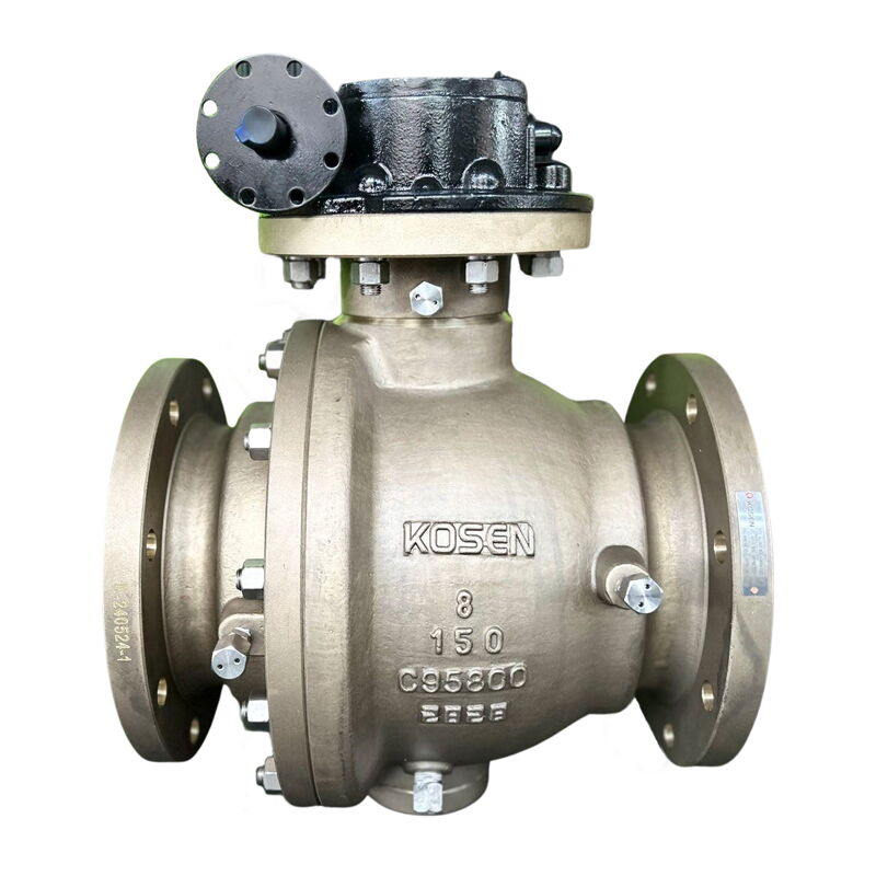
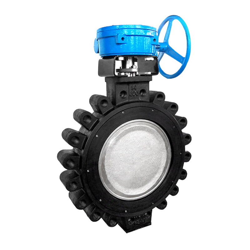
Quarter-turn electric actuators are designed to rotate an output shaft through a limited angular range, most commonly 90 degrees. This motion corresponds closely with the operating principle of many rotary valves. Ball valves, butterfly valves, and certain plug valves use a rotating closure element, so a quarter-turn actuator can directly or indirectly transmit rotational torque to the valve stem.
Their compact construction and relatively short operating time make quarter-turn actuators particularly attractive for applications requiring rapid valve opening and closing. Depending on the actuator design, gear transmission can amplify motor torque while maintaining a compact housing. Manual override mechanisms are also commonly incorporated so that operators can operate the valve during power loss or commissioning.
Typical characteristics include:
- Compact and lightweight construction
- 90-degree or other limited-angle rotation
- High operating speed
- Suitable for rotary valves
- Simple installation and maintenance
- Available for both on-off and modulating service
- Easy integration with position feedback and remote control systems
For butterfly valves, the actuator must overcome the torque generated by disc friction, fluid forces, seat compression, and differential pressure. For ball valves, the required torque can vary considerably according to seat design, pressure, temperature, media, and valve construction. Consequently, actuator sizing should be based on the actual valve torque curve rather than a generic valve diameter alone.
Linear electric actuators transform motor rotation into straight-line movement. A common mechanical arrangement uses a motor connected to a gearbox and screw mechanism, where a lead screw or ball screw converts rotational movement into axial displacement. The resulting linear force can move a valve stem upward or downward with controlled positioning.
Linear movement is particularly suitable for valves whose closure element travels along the valve axis. Depending on the valve design, this can include certain globe valves, control valves, diaphragm valves, and other valves requiring direct stem displacement. In automated control applications, linear actuators can provide precise stroke positioning, making them suitable for applications where flow must be continuously regulated rather than simply switched between open and closed states.
The major engineering advantage of a linear actuator is its ability to generate and control thrust. Unlike rotary applications where torque is the primary mechanical parameter, linear applications require careful consideration of stem force, seating force, differential pressure, packing friction, and mechanical resistance.
Important selection factors include:
- Required valve stroke
- Maximum and minimum operating thrust
- Valve stem diameter and connection
- Required positioning accuracy
- Operating speed
- Duty cycle
- Ambient temperature and environmental protection
- Required fail-safe or manual override functions
A linear actuator should therefore be selected using the valve manufacturer's required thrust and stroke data rather than simply converting a nominal torque value from another actuator category.
Multi-turn electric actuators are designed to rotate their output shafts through multiple complete revolutions. Unlike quarter-turn actuators, they are intended for valves in which substantial stem travel is required to move the closure element between fully open and fully closed positions.
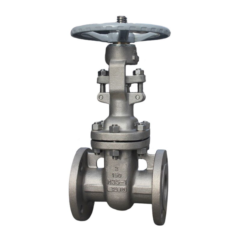
Gate valves are a typical application. A gate valve may require many turns of the stem to move the wedge through a relatively long stroke. Multi-turn actuators provide the necessary rotational displacement while generating high torque through a gearbox. They are also widely used in large-diameter valves, power plant systems, water infrastructure, and other applications where operating resistance and stem travel can be substantial.
Multi-turn actuators are often equipped with sophisticated position and torque monitoring systems. These features can allow the actuator to stop at defined travel limits, detect excessive mechanical resistance, and communicate valve status to a distributed control system or supervisory control system.
Because the actuator may need to withstand high loads for extended operating periods, mechanical transmission design becomes particularly important. Gear quality, lubrication, bearing capacity, housing strength, thermal management, and protection against environmental contamination all contribute to long-term reliability.
The relationship between actuator motion and valve construction is the foundation of correct selection. The actuator is not an independent power source that can be universally connected to any valve. Instead, it forms a mechanical system with the valve, and both components must have compatible output and input characteristics.
| Actuator Type | Output Motion | Typical Valve Types | Primary Mechanical Parameter |
|---|---|---|---|
| Quarter-turn | Approximately 90° rotation | Ball, butterfly, plug valves | Torque |
| Linear | Straight-line travel | Control, globe, diaphragm and similar valves | Thrust |
| Multi-turn | Multiple revolutions | Gate and other multi-turn valves | Torque + stem travel |
This table provides a useful first-level selection framework, but actual engineering decisions require more detailed analysis. Valve size, pressure class, fluid characteristics, operating temperature, differential pressure, seating design, stem configuration, operating frequency, and required control accuracy can all influence actuator requirements.
For example, two butterfly valves of the same nominal diameter may have significantly different operating torque because of differences in seat construction and disc geometry. Similarly, two gate valves with the same nominal diameter and pressure class may require different actuator torque because of wedge design, stem configuration, packing friction, and pressure differential.
Torque is the rotational force required to turn a valve stem or actuator shaft. For rotary valves, actuator torque must be sufficient to overcome every relevant resistance throughout the valve's operating range. This includes static friction, dynamic friction, seat deformation, packing resistance, bearing friction, and fluid-induced forces.
The actuator's rated torque should not be treated as an isolated number. Engineers should compare the actuator output torque with the valve's required torque curve. The highest required torque may occur at valve opening, closing, or an intermediate position depending on valve design.
A practical sizing approach should consider:
- Breakaway torque
- Running torque
- Seating torque
- Unseating torque
- Maximum differential pressure
- Temperature effects
- Media characteristics
- Packing and seal friction
- Allowable safety margin
The safety margin should be sufficient to accommodate realistic variations but should not be excessively large. Oversizing an actuator can create its own problems, particularly when the valve or stem cannot tolerate excessive mechanical force.
For linear actuators, thrust is the equivalent mechanical requirement. The actuator must generate enough axial force to overcome valve resistance and achieve reliable seating or positioning.
Thrust requirements can increase substantially under high differential pressure. Packing friction may also become important, particularly when the valve operates frequently or when the packing has been tightened excessively. In control valve applications, actuator thrust must additionally account for the force generated by the fluid acting on the plug, disc, or other throttling element.
A properly engineered system should consider the complete load profile rather than only the maximum nominal force. Excessive actuator thrust can damage valve components, packing, stems, seats, or mechanical connections, while insufficient thrust can result in incomplete closure, leakage, unstable positioning, or failure to overcome friction.
The mechanical transmission system is another major difference between actuator categories. Electric motors generally operate at speeds much higher than those required by industrial valves. Gearboxes, worm gears, spur gears, planetary gears, screw mechanisms, or other transmission components are therefore used to reduce motor speed and increase usable output torque or thrust.
Quarter-turn actuators often employ compact gear trains or worm gear mechanisms. The reduction ratio is selected to provide sufficient torque while maintaining acceptable operating speed. Some designs use self-locking worm gear arrangements, which can help maintain valve position when electrical power is removed, although the suitability of this characteristic depends on the specific application and safety philosophy.
Linear actuators commonly use screw mechanisms to transform rotary motion into axial movement. Lead screw systems are mechanically robust and suitable for many industrial applications, while ball screw arrangements can provide high efficiency and precise positioning where appropriate.
Multi-turn actuators generally incorporate multiple stages of reduction because high torque and controlled multi-revolution output are required. The transmission system must withstand repeated loading, particularly in large valves or demanding process environments.
Actuator selection is not simply a question of obtaining the highest possible operating speed. Fast movement can be beneficial for emergency isolation or process sequencing, but excessive speed may create water hammer, pressure surges, mechanical shock, or unstable control behavior.
For example, rapidly closing a large butterfly valve in a long water pipeline can generate significant hydraulic transients. In such applications, controlled closing speed may be more important than achieving the shortest possible stroke time. Similarly, in HVAC systems, an actuator that moves too aggressively can cause temperature or differential-pressure fluctuations.
For modulating applications, positioning accuracy is often more important than raw operating speed. The actuator should respond smoothly to the controller's command and maintain stable intermediate positions without excessive hunting.
Modern actuators may support proportional control signals such as 0–10 V, 2–10 V, or 4–20 mA depending on the specific product and control architecture. Digital communication can additionally provide position, torque, alarm, diagnostic, and maintenance information to higher-level automation systems.
On-off service requires the actuator to move the valve between defined positions, normally fully open and fully closed. The primary objectives are reliable operation, appropriate operating time, sufficient torque or thrust, and dependable end-of-travel detection.
Quarter-turn electric actuators are frequently used for automated ball and butterfly valves in this type of application. Multi-turn actuators are commonly used for automated gate valves, especially in large process systems.
Although the control logic is relatively simple, the actuator still needs to be correctly sized. An actuator that repeatedly approaches its maximum torque rating may experience excessive heating or mechanical wear, especially under frequent cycling.
Modulating service requires the actuator to position the valve at intermediate points according to a process signal. This places greater demands on positioning accuracy, repeatability, response characteristics, feedback systems, and control stability.
Applications include flow regulation, pressure control, temperature control, level control, and differential-pressure management. In HVAC systems, electric actuators may operate control valves continuously to balance heating or cooling demand. In process plants, modulating valves can maintain process variables within tightly defined operating ranges.
For these applications, actuator selection must consider the entire control loop rather than the actuator alone. Valve flow characteristics, controller tuning, actuator deadband, response time, feedback resolution, and process dynamics all influence final system performance.
Industrial valve actuators are often installed outdoors, in mechanical rooms, process plants, water treatment facilities, or locations exposed to dust, moisture, chemicals, and temperature variations. Environmental protection should therefore be considered during selection.
Ingress protection ratings such as IP65, IP66, or IP67 may be relevant depending on actuator design and installation conditions. However, the correct rating should be selected based on actual exposure rather than simply choosing the highest available rating.
Cable glands, electrical enclosures, terminal compartments, shaft seals, and cover gaskets can all influence environmental reliability. Improper cable entry installation can compromise an otherwise well-protected actuator.
Ambient temperature can affect motor performance, lubrication, electronic components, seals, and battery-backed systems. Low-temperature environments may increase lubricant viscosity, while high temperatures can accelerate insulation aging and electronic component degradation.
Where actuators are installed in potentially explosive atmospheres, standard industrial actuators may not be suitable. Appropriate hazardous-area certification and equipment classification must be evaluated according to the site requirements and applicable regulations.
This is particularly important in oil and gas, petrochemical, chemical processing, and certain mining applications. Hazardous-area suitability should be verified as a complete equipment specification rather than assumed from the actuator's general industrial appearance.
One of the most common mistakes is selecting an actuator based primarily on nominal valve diameter. Valve size is useful for identifying the general equipment category, but it does not determine the actual operating torque or thrust.
A DN300 butterfly valve, for example, may require significantly different torque depending on pressure rating, seat material, disc geometry, differential pressure, and operating conditions. Valve manufacturers' torque or thrust data should therefore be the starting point for final actuator sizing.
Another common mistake is assuming that a higher torque rating automatically means a better actuator. Excessive actuator capacity can damage valve components or increase mechanical stress. It can also make the system more expensive and potentially reduce control resolution.
The objective should be to provide sufficient capacity with an appropriate engineering margin, not to maximize the actuator rating regardless of actual requirements.
An actuator used twice per month has a very different duty requirement from one that cycles hundreds of times per day. Frequent operation increases motor heating, gear wear, contactor switching, and mechanical fatigue.
Duty classification, motor thermal characteristics, permissible starts per hour, operating time, and modulation requirements should therefore be included in the selection process.
Power failure, commissioning, maintenance, and emergency intervention may require manual operation. A suitable manual override can improve system maintainability and operational flexibility.
However, the manual mechanism must be designed so that it does not create unsafe operating conditions. Interlocks and operating procedures should prevent accidental simultaneous motor and manual operation where such a condition could damage the equipment.
A systematic selection process can significantly reduce actuator mismatch and premature failures.
First determine whether the valve requires quarter-turn, linear, or multi-turn movement. This immediately eliminates incompatible actuator categories and provides the foundation for further specification.
Collect the valve manufacturer's actual torque or thrust requirements, including breakaway, running, seating, and unseating loads where applicable. Do not rely exclusively on nominal valve size.
Determine the required angular rotation, linear stroke, or number of output revolutions. Then establish acceptable opening and closing time based on process requirements and hydraulic or mechanical limitations.
Specify whether the actuator will operate in on-off, positioning, or continuous modulating service. Also determine expected cycles, operating frequency, and duty duration.
Evaluate ambient temperature, humidity, dust, water exposure, corrosion, vibration, hazardous-area classification, and installation orientation. Select enclosure and protection characteristics accordingly.
Determine the required electrical supply, control signal, local controls, remote commands, position feedback, torque monitoring, communication protocol, and alarm functions according to the automation architecture.
Check the actuator-to-valve mounting interface, shaft or stem dimensions, coupling arrangement, flange pattern, available installation space, and manual override configuration.
Evaluate fail-safe requirements, emergency shutdown functions, limit switches, torque protection, thermal protection, interlocks, and loss-of-power behavior. The actuator should support the safety philosophy of the complete valve system.
| Factor | Quarter-Turn | Linear | Multi-Turn |
|---|---|---|---|
| Main movement | Limited rotation | Straight-line travel | Multiple rotations |
| Typical valves | Ball, butterfly, plug | Control, globe, diaphragm | Gate and multi-turn valves |
| Main load | Torque | Thrust | Torque and stem load |
| Typical advantage | Compact and fast | Precise linear positioning | High load and long travel |
| Common application | Isolation and rotary control | Modulating control | Large or high-resistance valves |
| Main sizing concern | Valve torque curve | Valve thrust and stroke | Torque, travel, and duty |
| Typical complexity | Low to medium | Medium | Medium to high |
The table should be regarded as a selection guide rather than an absolute classification. Some valve designs use mechanical gearboxes or special couplings that change the actuator interface. Certain rotary control valves may also require precise modulation rather than simple 90-degree operation. Therefore, the actual manufacturer's valve-actuator interface specification always takes precedence over a general classification.
Correct actuator selection has a direct effect on equipment reliability. A properly sized actuator operates within a reasonable portion of its mechanical and thermal capacity, reducing unnecessary stress on motors, gears, bearings, couplings, and valve stems.
The benefits extend beyond the actuator itself. Stable valve positioning can improve process control, reduce pressure fluctuations, prevent unnecessary energy consumption, and minimize maintenance interventions. In HVAC systems, accurately controlled valves can contribute to better hydraulic balancing and pump energy management. In industrial process systems, precise automated valve movement can help maintain stable flow, pressure, temperature, and production conditions.
Preventive maintenance should also be adapted to the actuator type. Quarter-turn actuators may require inspection of gear mechanisms, shaft couplings, limit switches, and sealing components. Linear actuators require attention to screws, nuts, stem alignment, lubrication, and thrust transmission. Multi-turn actuators require careful monitoring of gearbox condition, torque settings, travel limits, lubrication, and mechanical connections.
The development of industrial automation is gradually transforming electric actuators from simple motor-driven devices into intelligent field equipment. Modern smart actuators can incorporate microprocessors, digital position sensing, torque measurement, diagnostic functions, event logging, and network communication.
This capability allows maintenance teams to obtain information beyond simple open or closed status. Abnormal torque, excessive operating cycles, repeated thermal trips, positioning errors, or unusually long travel times can indicate developing mechanical or process problems.
When integrated with PLC, DCS, SCADA, or building automation systems, intelligent actuators can become part of a broader condition-monitoring strategy. This is particularly valuable in large facilities where manual inspection of every automated valve is impractical.
However, smart functions should not replace fundamental mechanical selection. Advanced diagnostics cannot compensate for an actuator that has the wrong motion type, insufficient thrust, inadequate torque, or an incompatible mounting interface. Correct mechanical matching remains the foundation; intelligent control builds on that foundation.
The most reliable actuator selection philosophy is to start with the valve and operating conditions rather than the actuator catalog. Engineers should first understand how the valve moves, how much torque or thrust it requires, how far it must travel, how frequently it operates, and what environmental conditions it will experience.
From there, the actuator category becomes much clearer. Quarter-turn actuators are generally the logical choice for rotary valves requiring limited angular movement. Linear actuators are appropriate when controlled axial displacement and thrust are required. Multi-turn actuators are suited to valves requiring multiple rotations, high torque, or substantial stem travel.
The final objective is not to select the largest, fastest, or most technologically advanced actuator. It is to select the right actuator for the actual duty. This approach balances performance, reliability, control accuracy, energy consumption, installation requirements, and lifecycle cost.
Understanding motion is therefore more than a basic classification exercise. It provides the engineering logic connecting the valve, actuator, control system, and process. Once the required output motion is correctly identified, torque or thrust can be calculated, speed and duty can be defined, environmental conditions can be evaluated, and control requirements can be integrated. In this sense, understanding how an actuator moves is the first step toward knowing which actuator will work best.